
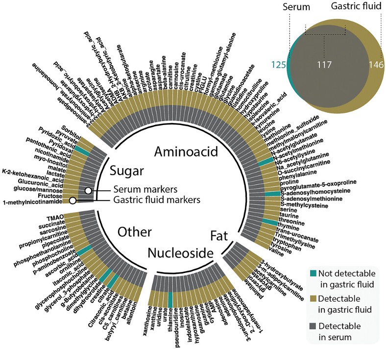
In situ continuous monitoring of systemic gastric biomarkers


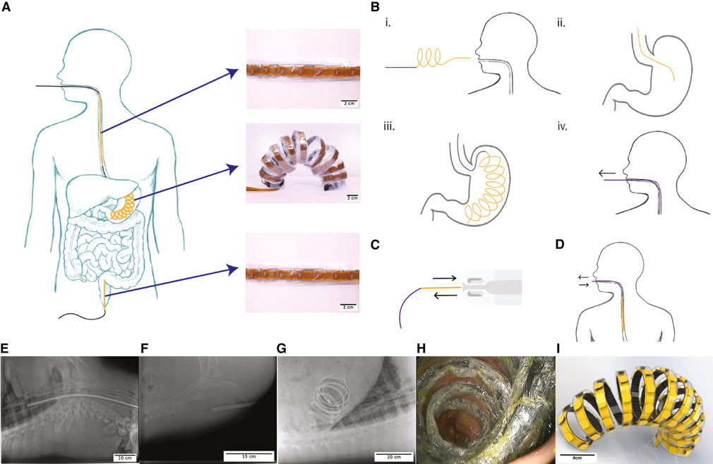
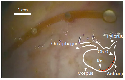
Advanced medical devices and sensors for gastrointestinal health monitoring
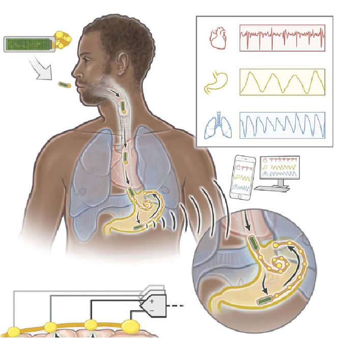
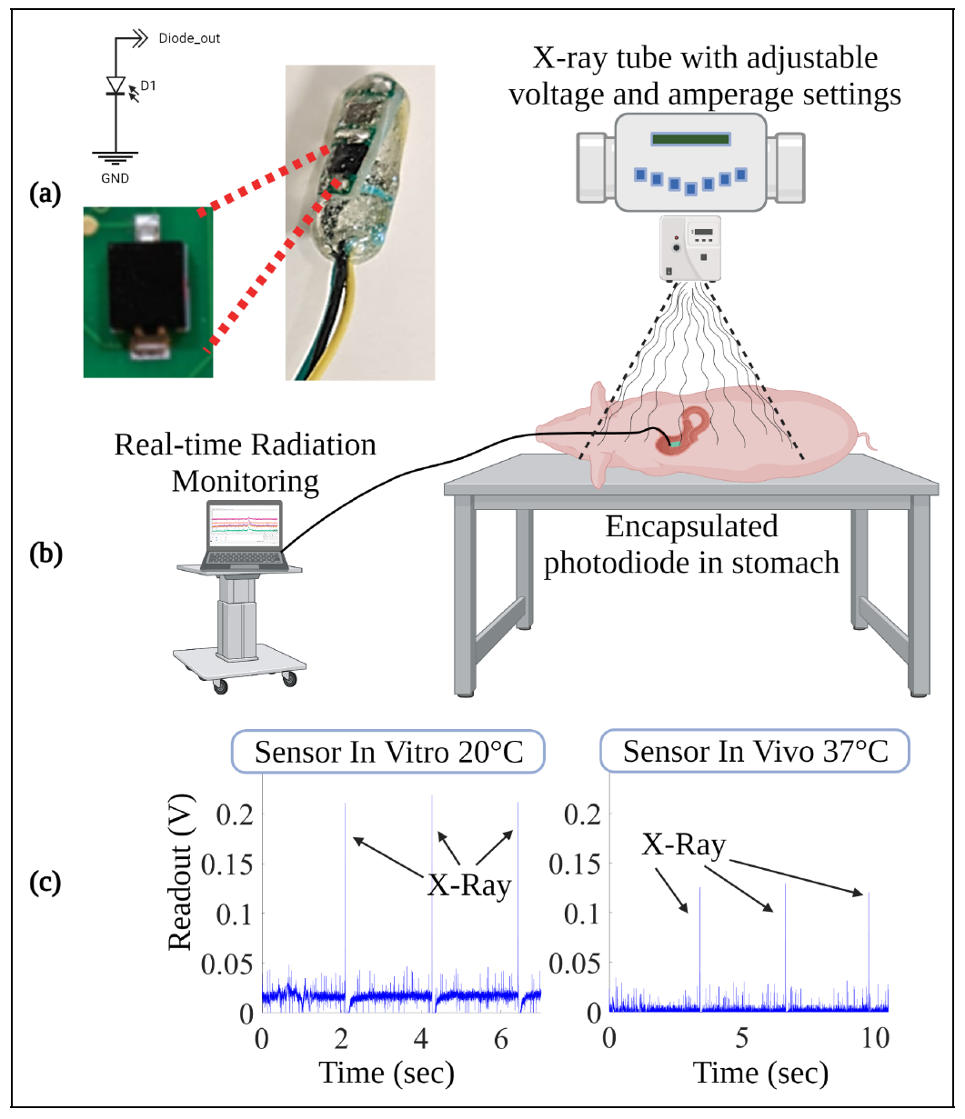
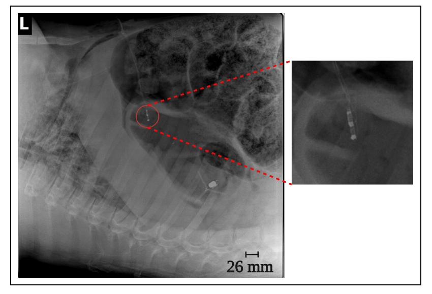
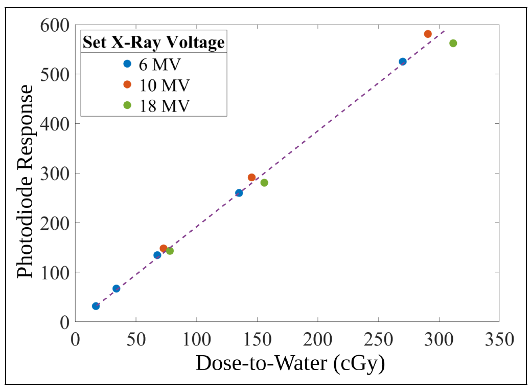
Our research focuses on developing electrochemical gas sensors for real-time detection of inflammatory biomarkers in the gastrointestinal tract. These sensors enable early detection and monitoring of inflammatory conditions.